The Famicom system
PlayPower
PlayPower was the idea to use low-cost Famiclone systems with built-in keyboards to serve as a learning platform for underprivileged children. These devices were readily available in many areas of the world, at a fraction of the cost of any of the various educational platforms proposed and developed around that time.
The concept struck me (and others) as genius. The project started with a lot of enthusiasm, received broad public attention, six-figure funding, and like many educational projects, went absolutely nowhere.
It did, however, give me an idea. PlayPower or not, the Famiclones were there, and if they can be used to teach typing, they can also be used to teach programming.
DEVROM and DEVBASIC
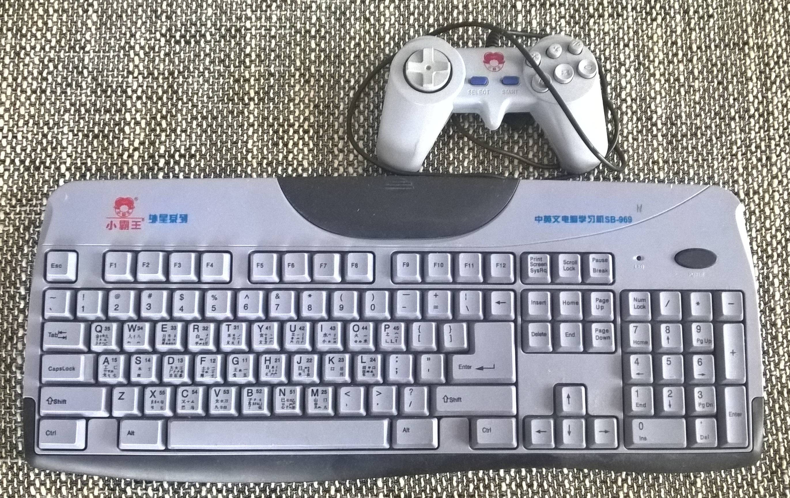
I went ahead and got my hands on a keyboard-style Famiclone manufactured by a company called "Subor". These were the same models that PlayPower hackers used for their research, and they had rudimentarily documented the idiosyncratic extensions of the standard Famicom cartridge connector that Subor had added and that made it possible for them to package a cartridge with educational content with the device that only consisted of one memory chip and did not require fancy circuitry.
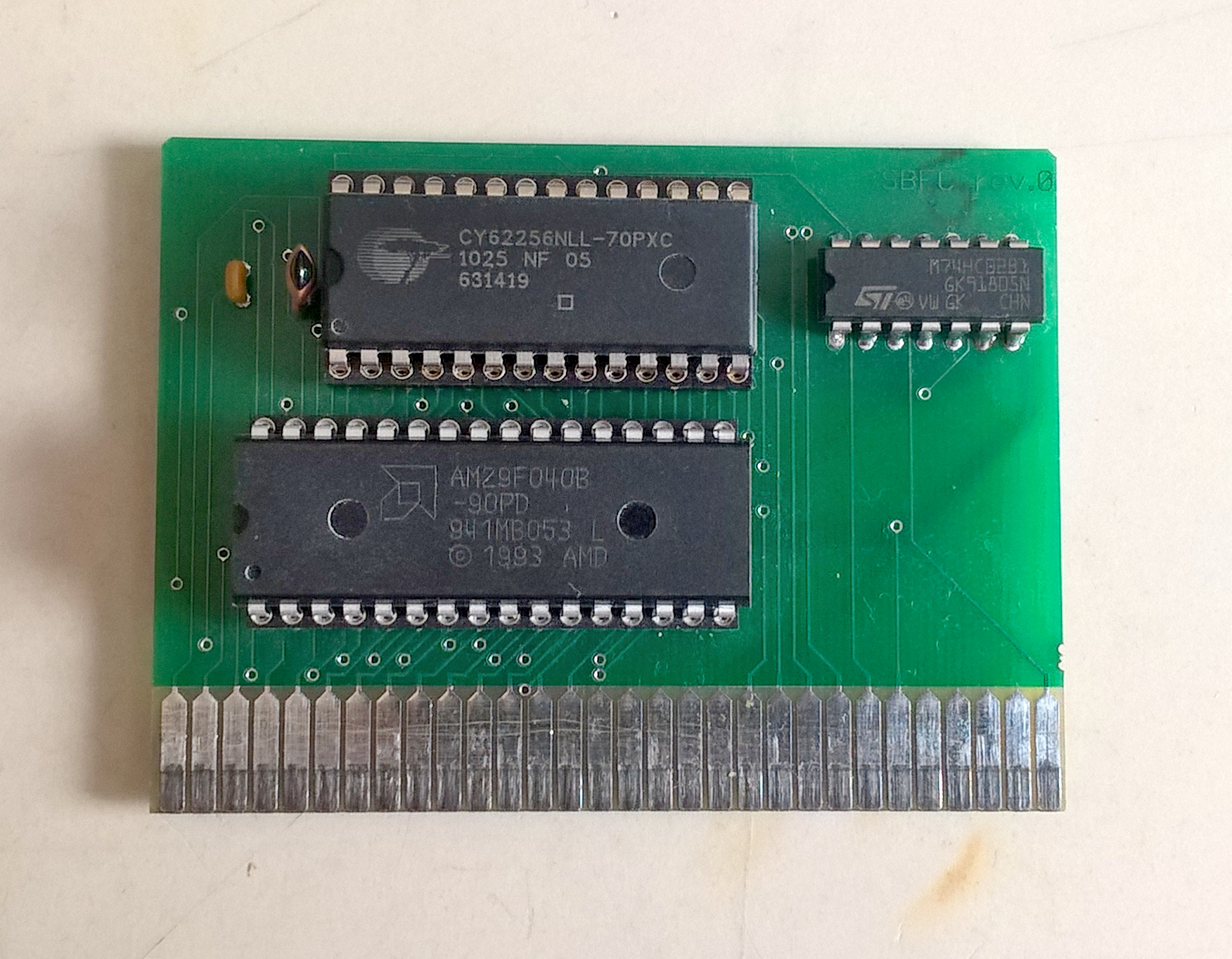
Armed with that information and a lot of my own research, I went ahead and prototyped my own cartridge that included a flash ROM and a static RAM chip that would allow me to develop a kick-ass home computer that would be fun and easy to program, while being affordable to most people. (I had never done anything like that before.)
Based on a BASIC interpreter for 6502 systems called EhBASIC, I developed a simple operating system and BASIC programming environment with all the fancy features you could want, sprites and everything. I showed it to some people. They didn’t care. I gave up on it.
As it turned out, I made a strategic mistake. More on that later.
Obsolescence
After years of it sitting on a shelf, my wife encouraged me to pick this project up again. After such a long time, however, the keyboard-style Famiclones had largely been phased out, replaced by more modern, more expensive and less hackable systems. My cartridge, designed for the proprietary Subor cartridge port, was obsolete.
One thing that had not died, however, was the Famicom platform. Famiclones have been built since the beginning of time, and unlike the original system or the keyboard clones, nobody ever saw any reason to stop building them. And I don’t think anybody ever will.
|
Note
|
If you are a fellow European, you may not realize what a gigantic deal the Famicom is to the rest of the world. Not only was it the biggest thing in its native Japan and the United States (in the shape of the NES), it is the world’s video game system, with Chinese-made clones and unlicensed cartridges available in the farthest corners of the planet, and still in production to this day. |
Famicom Legacy
So I decided to go back to the basics and design a cartridge that would work with a standard Famicom system.
Unlike the VT02 Famicom-on-a-chip that the Subor keyboard Famiclones had been built around, a standard Famicom system does not have support for large memories, and it obviously does not have a keyboard. I had to find a way to make these work, and after researching a lot of old-ass Famicom cartridge designs and thinking how to solve things in software, I came to the conclusion that I had to design my own memory mapper chip. (I had never done anything like that before.)
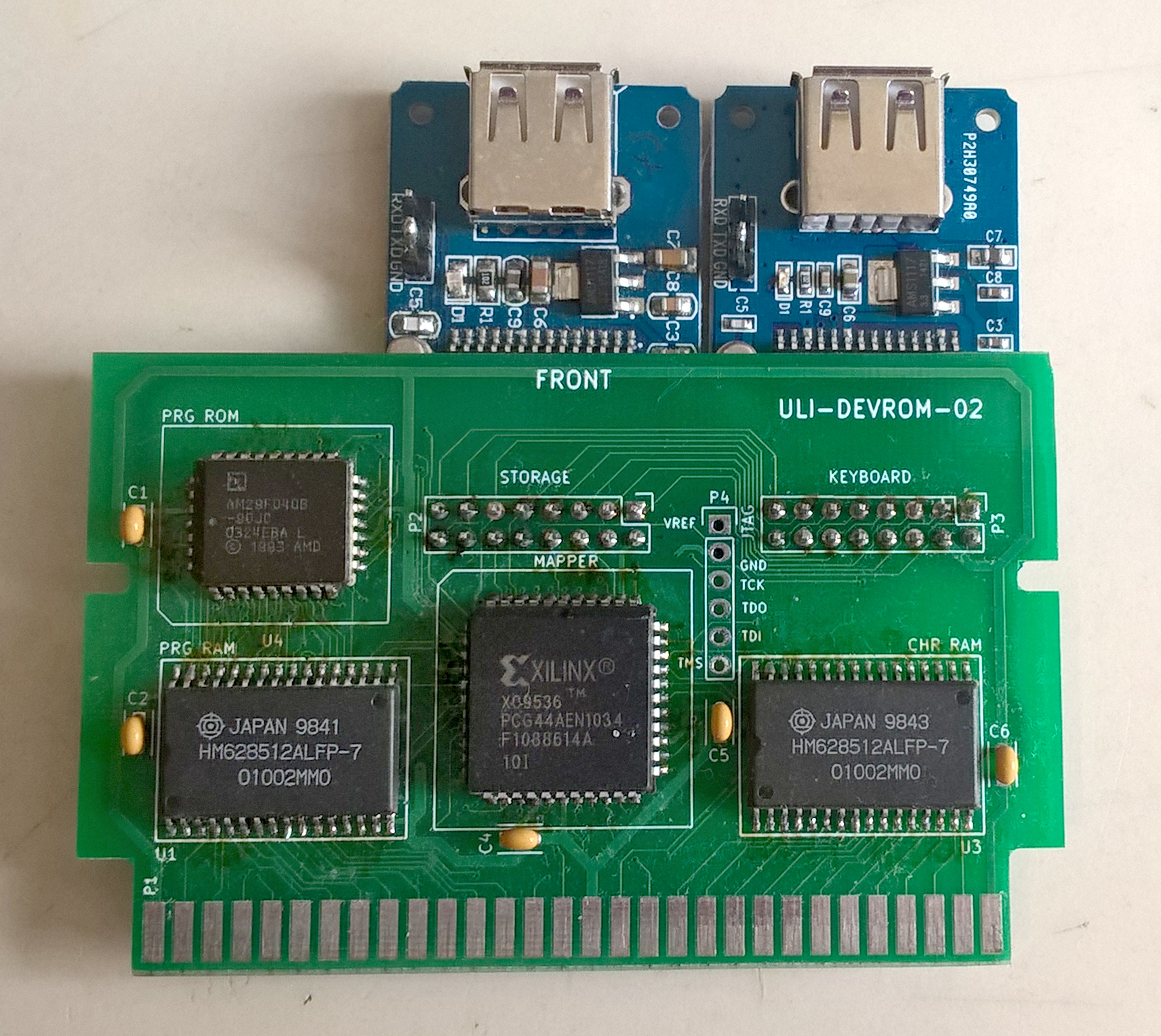
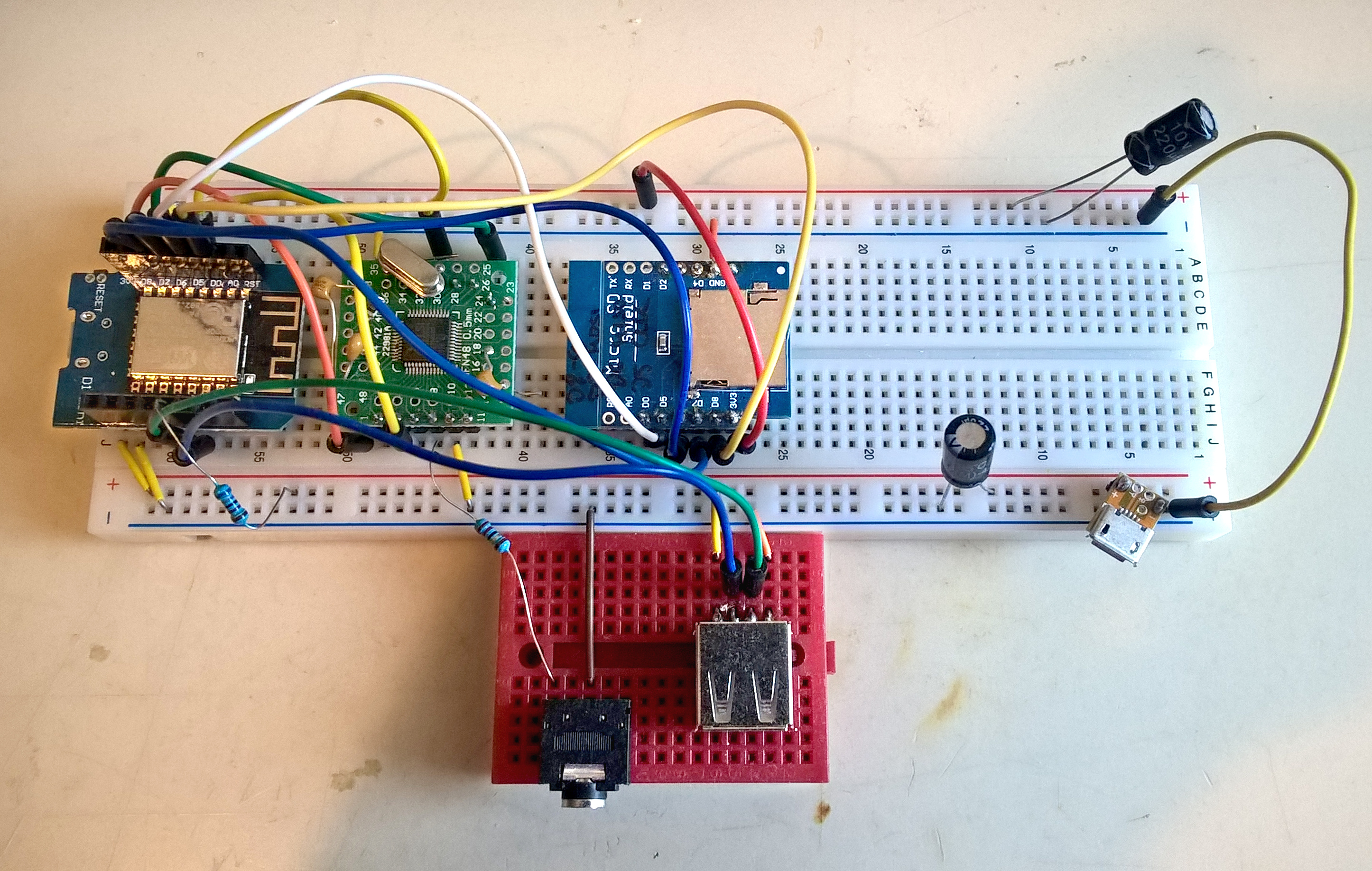
The daughterboards carry CH376S USB host controllers.
Live testing
Chugging away, I added all the features you could want in such a system: graphics, sound, sprite editor, C compiler(!), USB storage and keyboard interface. It was brilliant!
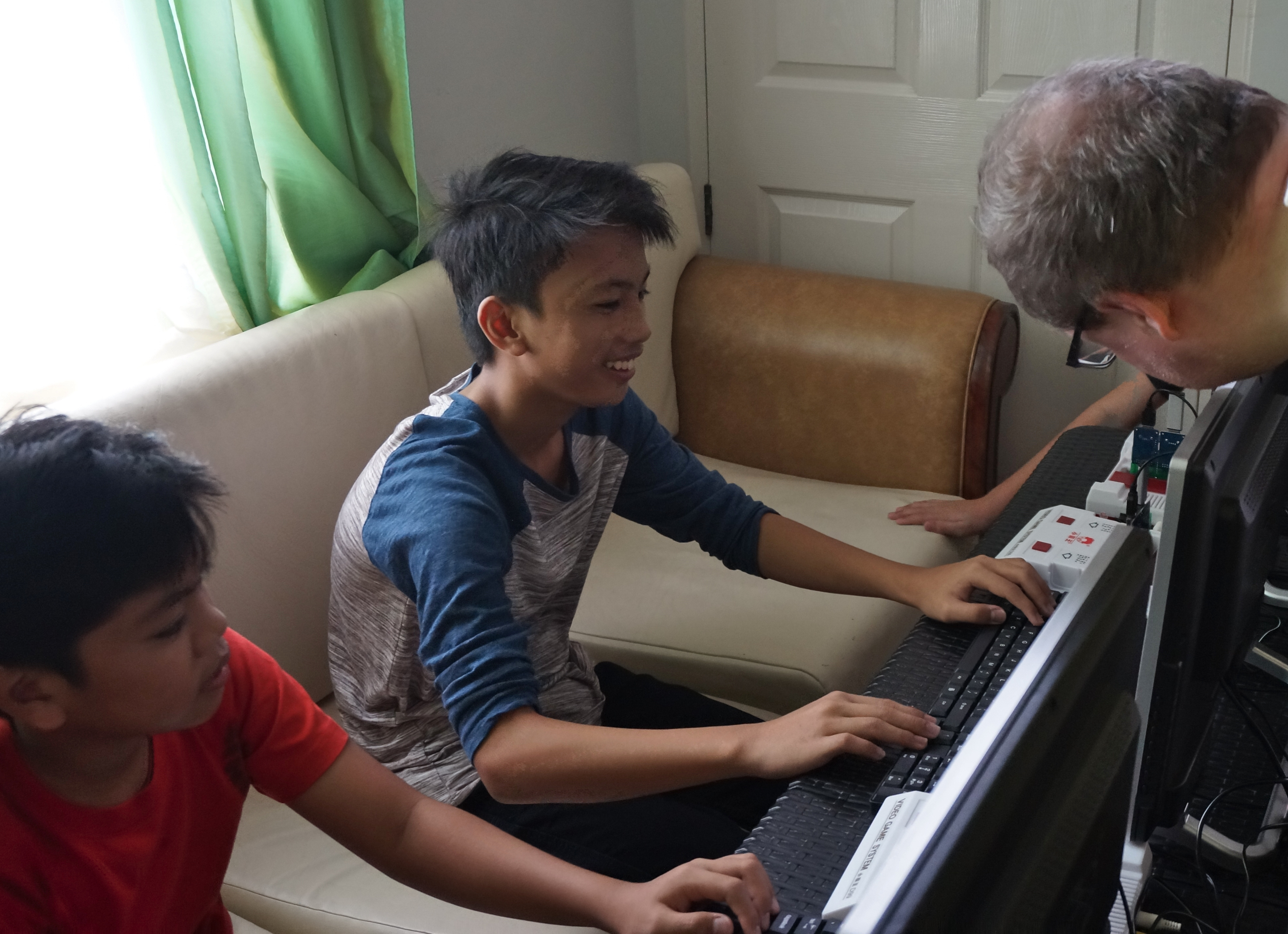
At some point I wanted to see if anybody cared after all. Remember the strategic mistake I alluded to earlier? I had only shown the system to adults. Here’s the secret: Adults don’t know shit. I had to talk to real people. So I enlisted my wife and my sister-in-law to round up some kids from the neighbourhood for me to experiment on.
They loved it. Want to see a twelve-year old’s jaw drop? Tell them this:
-
Enter
PRINT "Hello!". -
Enter
10 PRINT "Hello!", then enterRUN. -
Enter
20 GOTO 10, then enterRUNagain.
There was a slight catch, though: You may have noticed that I frequently use the phrase "I had never done anything like that before."
That came back to bite me.
It turns out that there are a lot of things you can do wrong when designing digital circuits, and the most likely errors are in the non-digital part. At least if you’re a software engineer, like I am. In this case, it was the power supply. (Cue hardware guys: "It’s always the power supply, mate.")
USB thumb drives can draw a lot of current. So can USB keyboards and CPLDs (that’s what my memory mapper chip was made of). Famiclones do not draw a lot of current. The power supplies that came with the Famiclones were designed for Famiclones. See the problem?
Well, I didn’t. Until one of the kids said, "My program is gone!". It was. And when he typed it in again and saved it again, it was gone again. I figured out what was happening eventually: the USB drive used much more power when writing than when reading or sitting idle. When you saved a program, the power draw would rise quickly, and the voltage would collapse momentarily, causing the write to fail. I knew what was going wrong, but I had no way of moving forward. I wasn’t at home, I had no tools, no parts, and no way of fixing this. I had to abort.
The Limits to Growth
Back home, I decided to re-design my cartridge to make sure that didn’t happen again. I also wanted to tie some loose ends in the software, make sure that all errors are handled properly, for instance. It seemed like pretty straightforward stuff. But it wasn’t.
Despite my fancy memory mapper chip, the basic architecture of the Famicom stays the same. You only have 32 kB of ROM visible at one time, and if your program is bigger (DEVBASIC was way bigger than that), you have to switch things around, bring in the bits you need on demand. Some parts of your program have to stay put, however, because they can be needed at any time, such as interrupt handlers. In practice, you only have 16 kB of ROM that you can switch around. That isn’t much, and Famicom programmers have all sorts of tricks up their sleeves to work around this limitation.
So in theory, the problem could be solved, but I knew the code base, and I knew that fixing EhBASIC in particular would be extremely tricky. Yet I soldiered on. Every tiny bit of additional code required me to make room for it, by rewriting other parts, making them smaller, moving them around. It was super painful, and at some point I realized that I would not be able to add even the most basic error handler anymore without what effectively amounted to rewriting the whole thing.
Cheating
I had always aimed to make my system an honest one. I do not like systems that put you in a playpen, just because you are a beginner. I wanted to make a go-kart: it may not be powerful, but you can just get in and step on the gas, and when you do it gives you all it’s got, and you will feel every bump on the track.
The problem is that a go-kart will stop moving when you load it with a ton of baggage, and likewise did the Famicom ache under the load that USB drivers, file systems, interpreters, compilers, and even error messages put on it.
So I thought, hey, what if we offload some of that stuff? There are these cheap microcontrollers (MCUs) nowadays, and one of those could handle the USB hardware. Could do the file system, too. Maybe it could run the C compiler; the code it produces would still run on the Famicom, so it wouldn’t be a fake, right?
I went ahead and designed a new board. I used a bigger CLPD for the mapper, and added an SPI controller written in VHDL to it, to talk to a modern MCU. (I had never done—well, you get the idea by now…)
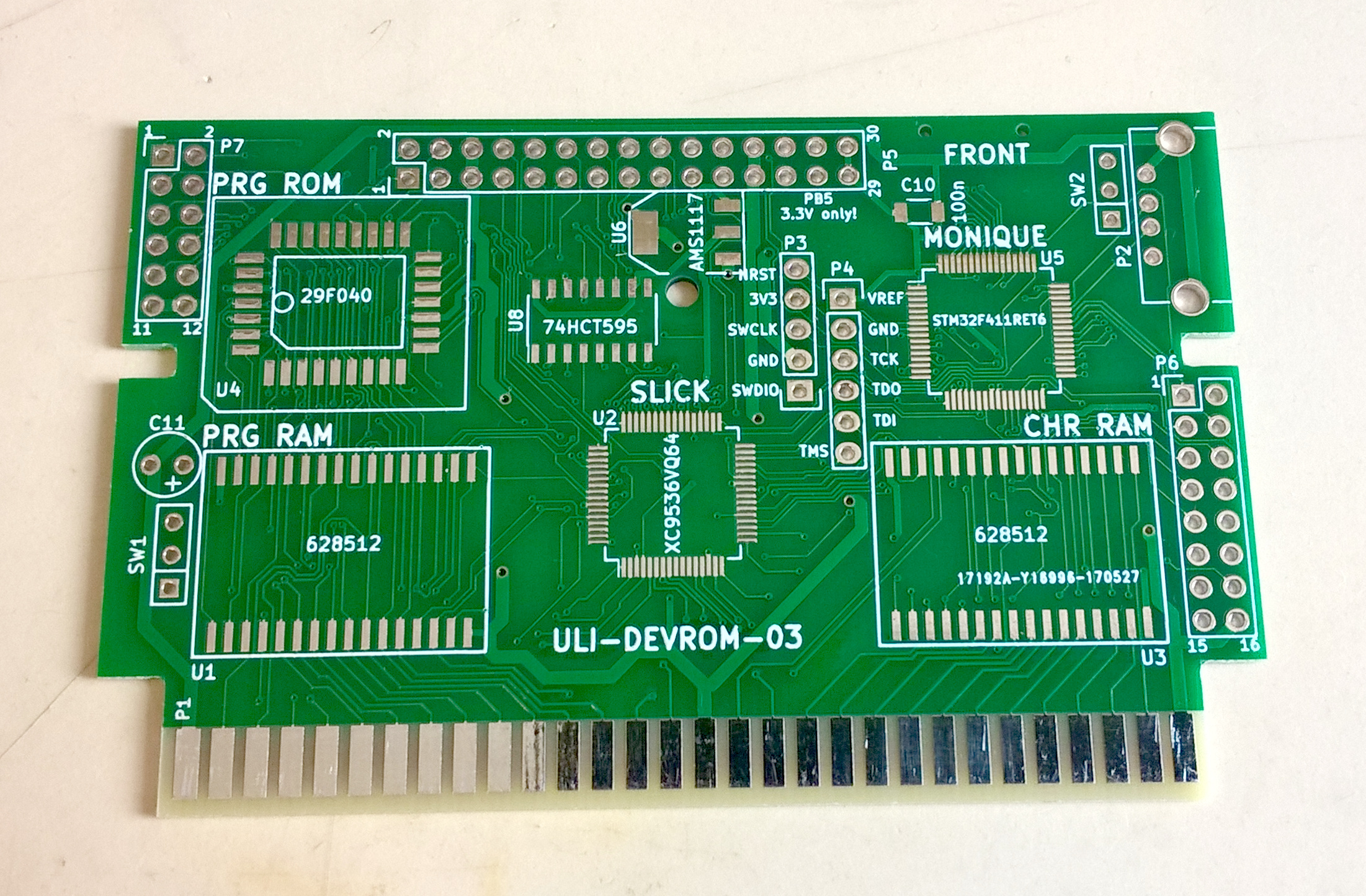
I picked an STM32F411 MCU to replace the USB controllers and to do all the USB and file system stuff. Now I had a 1.79 MHz Famicom doing the heavy-duty multimedia stuff, assisted by a 100 MHz MCU waiting for key presses. It felt odd.
After removing all the things from the Famicom that were now handled by the STM32F411, I had saved all of 8 kB, out of 130 or so. Worse yet, the BASIC interpreter didn’t shrink by a single byte. I still had to rewrite everything.
I began to wonder how well a BASIC interpreter would work if it ran on the STM instead of the Famicom’s 6502. Of course I had no intention to replace the native BASIC interpreter with anything like that. It would be fake, totally unacceptable! But just out of curiosity, I wanted to have a look. I took the first BASIC interpreter written in C that I could find and ported it to the STM and the NuttX operating system.
It ran fifty times faster.
At this point I had built a go-kart that not only depended on a support truck, but was remote-controlled by one. My system, the system I had spent years to develop, simply didn’t make any sense.
The BASIC Engine
It became more and more clear to me that the only reasonable way forward was to drop the Famicom. I haven’t had any emotional attachment to it in the beginning, but it had grown on me. Not to mention that little of the software I had developed would translate easily to any other machine.
It was painful, but it had to be done. But what was to take its place?
Toyoshiki Tiny BASIC
An STM32F411 might be capable of handling all the I/O and computing on a single buttcheek, but it lacks the visuals and the sound. It lacks what gives a computer its personality, what makes a Famicom, a PC Engine, a ZX Spectrum and a Commodore 64 instantly recognizable.
I looked through the depths of the Internet for a solution. Maybe somebody had already figured it out? In doing so, I came across an unnamed system designed by a Japanese going by the name Tamakichi-san.
Using a BASIC interpreter written by Tetsuya Suzuki for the Arduino Uno, he (or she) came up with a system based around the so-called "Blue Pill" board. These boards, built around the STM32F103C8T6 MCU, are sold for small change on AliExpress, and Tamakichi-san’s design limits itself to adding a bunch of resistors and connectors to provide what is arguably a full-fledged personal computer, with all the peripherals you would expect: keyboard, video output, sound, storage, serial port.
A personal computer programmable in BASIC that hooks up to a TV and a keyboard and costs virtually nothing. Now I knew what I was aiming for.
Color Burst
The Toyoshiki Tiny BASIC system contains a number of very clever hacks required to achieve its amazing price-performance ratio, but the reliance on what the low-end STM32F103 controller has to offer limits its capabilities, especially in one area: the video output is black-and-white.
The Toyoshiki system uses the STM32F103’s timers and SPI controller to produce a video signal, containing the synchronization pulses and the luminance. It is not, however, capable of producing a color burst signal, which is required for a TV to display any sort of color in an analog video signal.
There are various similar projects (although none as ingeniously minimalistic as the Toyoshiki system) that implement video output in clever ways, but almost none of them produce a color video signal. The few that do heavily rely on carefully timed software (and are thus not usable as general-purpose computers) or add additional hardware video encoders, which typically cost several times more than a Blue Pill board.
I find black-and-white endlessly depressing, and I knew I would not be happy with a system that doesn’t have color. So I felt my only chance would be to be more clever than the rest of the world, and I went ahead to develop a system that produces color video without requiring expensive components or intricately timed code.
I came very close to implementing a system that uses two more of the STM32F103’s very capable timer circuits and only an external oscillator and some passive components to produce a color video signal. When I was almost done, I realized that it will not actually be that great.
For one, using my technique would give me a maximum of eight colors, and no control over saturation. Basically, it would look like a ZX Spectrum. Meh.
The bigger problem, however, was memory. While modern MCUs are more capable than the Famicom by orders of magnitude in many areas, they do not tend to come with a lot of RAM. It’s simply not necessary for the tasks they are typically used for. Pull the brakes. Open the valve. Blink the LED. Not much to remember there.
Showing graphics, on the other hand, gobbles up memory quickly, and showing color graphics even more so. Three times as much, in this case. The STM only comes with 20 kB of RAM, and when you subtract the memory required by the BASIC interpreter and the color graphics, you basically end up with nothing left for your program. Even if I got that to work, it would at best be a neat trick, but nothing anybody would actually be able to use for anything.
It became more and more clear that it would not be possible to get good graphics without extra hardware.
Panu’s Weekend Project
When you search for dedicated hardware to produce a video signal that you can hook up to an MCU without tying up most of its resources, you will find mostly nothing. Some devices are mere encoders, requiring a timed input signal that you have to create yourself, some are super-expensive (two figures), some are long obsolete, and the best are all of the above. HDMI, you say? Fewer obsolete components, but twice the price.
There was, however, one exception. And it was a perfect fit.
The VS23S010D-L by Finnish manufacturer VLSI is a static RAM chip with an SPI interface. Nothing special about that, there are literally hundreds of these. Except that this one comes with a video controller. That is a rather unusual feature for an SRAM, and when I read how it came about, it was immediately clear to me that this is what I’ve been looking for all along:
And at a meeting, our CEO asked if we had any other ideas for the product. And so I said that if we just add a couple of counters inside, we could make a pattern generator that could be useful for "various purposes". He said that should be ok, if indeed it was "just a couple of counters" and didn’t make the chip a testing nightmare.
…
I actually came to the lab during the weekend and wrote the configuration for a minimalistic NTSC modulator on that tiny CPLD. When our CEO saw it, he asked if we could fit it inside our IC. And I said, sure, its something like 10 to 20 flip-flops. But with a little more, we could make it much better. He asked how much better, and I said full color (my demo had 14 colors - sync level, burst level and 14 indexed colors formed with VHDL combinatorial logic statements). Of course we would need to put a DAC inside, but no problem, our company is expert with DACs.
Uzebox forum
Let that sink in for a moment: When they needed a gimmick to soup up their somewhat bland memory chip, they threw in a graphics controller. Because, you know, that doesn’t cost anything. It’s just a couple of gates. Did it on the weekend, no testing required. The VS23S010D-L video controller has a price-performance ratio of zero.

think up a texture mapping unit using fewer than five NAND gates.
Besides producing a color video signal, the VS23S010D-L solved another problem I ran into all the time: the lack of RAM. It comes with 128 kB, some or all of which can be used as a frame buffer. That frees up a ton of memory on the MCU that can be used for user programs instead. Perfect!
But even with the VS23S010D-L taking a lot of memory load off the shoulders of the MCU, the 20 kB RAM of the STM32F103 weren’t going to do it. Something with more punch was needed. But it couldn’t cost anything.
ESP8266
The search for an MCU with more memory and a cheap price point led me straight to the ESP8266.
The ESP8266 was developed by a company called Espressif as a low-cost WiFi-capable MCU, and was first used as a WiFi dongle connecting embedded systems to the Internet.
By the standards of your typical MCU, that is a formidable task. It requires giant protocol stacks, cryptography, radio, and all sorts of expensive things. Espressif made the ESP8266 just powerful enough to handle these things, no more.
When you program the ESP8266 using the Arduino platform, as most people do, it feels somewhat bloated and sluggish. For a "Hello, World!" program you have to upload more than 200 kB of code. There are extra hoops you have to jump through so it won’t crash after a few seconds. Power use, latency and performance are hard to predict. All in all, it’s quite awkward to use, but it’s cheap and has networking, and for many applications that makes up for its shortcomings.
Relieve it of the weight of WPA2/PSK, TLS, IPv4 and all that other network nonsense, though, and the awkward little controller roars. Charles Lohr, noted ESP8266 hacker with at best a shaky grasp on the meaning of the word "impossible", has run it at 378 MHz.
Meanwhile, Russian developer pvvx has conjured up an SDK culling all the network support and thus freeing virtually all of the ESP8266’s memory for application use. I went to graft the ESP8266 Arduino core onto it and started porting.
Noise
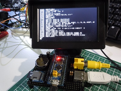
I had wired up a prototype on breadboards by now, and a quick port of Toyoshiki Tiny BASIC to the ESP8266 and a hacked-up video demo from VLSI later, it started to look like this could actually work!
So I had video and computing and an input device, but there was no sound yet. I already used two whole chips by now, and there was definitely no budget for a fancy audio codec. What to do?
Espressif provides a demo program for the ESP8266 SDK that streams MP3 audio from the network and sends it to an audio codec connected to the MCU’s I2S output, effectively resulting in something like a web radio. Knowing their customers, and never outdone when it comes to cheap, they included an option to replace the codec with a low-pass filter and use the I2S output for pulse-width modulation. Boom, two capacitors and a resistor later we have sound! Total cost: three cents.
Does it sound good? Hell, no. Calling it LoFi is being charitable. But it’s there, and it’s loud, and at the end of the day, that’s what counts.
Think of the Children
When Espressif designed the ESP8266, they clearly had some applications in mind: web radio, home automation, turning the lights on and off and the AC up and down over the Internet. Besides WiFi, you don’t need a lot of interfaces for those purposes: maybe an SPI port, a little I2C, an I2S, a few GPIOs, and an analog input to measure the humidity of your plants. No need to go overboard.
Contrast that with MCUs more geared towards industrial applications: The STM32F411, comparable in CPU power and memory size, has five SPI controllers, three "USARTs", three I2C controllers, USB OTG, five times I2S, and eleven(!) timers.
Nobody needs that much I/O, I certainly didn’t. But the minimalistic approach of the ESP8266 still turned out to be an issue. Having put all the pieces of the BASIC Engine together, a single general-purpose I/O pin remained unused and could be made available to the user.
I thought about it. So what if I’ll present the BASIC Engine to the public, and some kid comes along and says, "WTF, one GPIO? My dad’s Arduino Uno has more than that!" And instead of joining the peaceful forces of the BASIC Salvation Army, she walks by, straight into the arms of a recruiter for a military equipment manufacturer, spending her life developing drones that kill innocent people in Central Asia. Would I be able to live with myself after that?
I needed more I/O. It was a moral imperative.
Besides the moral aspects, I also thought about how to connect game controllers, Atari-style joysticks in particular. The problem was the same in the end, and the canonical solution to it is commonly called an "I/O expander". Such devices connect to a narrow bus on the MCU (like SPI or I2C) and have a lot of pins that can be controlled over that bus. They can also be really expensive.
Expansion
I/O expanders come in all sorts of specifications, and generally speaking, the faster they are, they more expensive they get. Sinking a lot of money into an I/O expander was not an option, so I looked at the low end of the performance range and tried to find the cheapest option.
Finding the "right" price for electronic components is not very easy if you don’t know where to look. Large Western electronics distributors, such as Digikey, Mouser or Farnell, charge you as much as they can get away with. If you buy a rarely-used component, you will be ripped off. If you buy a generic part, you will be ripped off. They wrap your tiny chip in about one cubic meter of packaging and then charge you insane amounts for shipping. The only thing you can learn from them is how much is too much. The only reason to buy from them is that somebody else foots the bill. If you consider buying from them because you need something immediately, check first if a plane ticket to Shenzhen is cheaper.
Yet another catch with major distributors is that while they offer a seemingly impressive variety of components, they do not stock products by some manufacturers at all. Among them are more often than not VLSI and Espressif…
Major Asian distributors usually do not give you any price to begin with, you need to request a quote, and I doubt that any first offer for a small number of components will be very good. Smaller local distributors, such as Reichelt in Germany or TME in Poland, occasionally have decent prices on some items, but they also have wildly overpriced ones, and usually a more limited selection than the larger companies.
eBay is completely useless. While it has decent offers when it comes to tools, it is with very few exceptions by far the most expensive place to buy electronic components from. Amazon does not have any offers worth speaking of.
No, my friend, the real price of electronics is on AliExpress.
AliExpress is the business-to-consumer retail web site of the Alibaba Group, a large Chinese business-to-business trading platform. Vendors on AE sell everything from glass beads and teddy bears to pick-and-place machines directly to consumers worldwide. On lighter items, such as electronics components, shipping is usually free. I get virtually all my parts and consumables from AE, and of course I looked there first.
A popular choice for an I/O expander is the PCF8574T. It connects to an I2C bus, provides eight I/O pins and costs about 22 cents per piece on AliExpress. For comparison, here are the prices from other places:
Mouser |
1.18 EUR |
Digikey |
1.23 EUR |
Farnell |
0.88 EUR |
TME |
0.89 EUR |
Reichelt |
0.94 EUR |
eBay |
0.33 - 7.23 EUR |
Amazon |
1.35 - 5.29 EUR |
While it seemed to be a decent choice, there was an even better one: the PCF8574T has a bigger brother called PCF8575TS, which is actually physically smaller, but provides 16 I/O pins, enough even to hook up a Neo Geo controller.
There was, of course, a catch.
Boxes and boxes
The most popular classic game controllers, such as the NES/Famicom, Super NES/Famicom or PlayStation 1 and 2 controllers, use a serial protocol to communicate. In theory, such a protocol could be run over the I2C I/O expander, were it not for the speed: for every bit transmitted, these protocols require the clock pin to be asserted, the data pin to be read, and the clock pin to be deasserted.
Each of these operations needs to be transmitted to the I/O expander, and the PCF8575, simple as it is, always requires all 16 bit states to be transmitted, every time. So we would have to transmit 48 bits for every bit of data, plus I2C protocol overhead, plus controller protocol overhead, over an I2C bus. I2C is not a very fast bus.
In computer terms, the whole ordeal adds up to roughly one eternity, plus-minus. We would spend our whole time talking to the game controller, not being able to do anything else.
I could have said, OK, whatever, just don’t support these controllers. But something told me that that would not be a good idea. Maybe it was the boxes full of PlayStation and Famiclone controllers knocking about my office, and the complete absence of any Atari, Sega or Neo Geo controllers. (I do have some, but certainly not enough to fill boxes.)
So serial controllers were mandatory, but there was no budget for a better I/O expander, and no pins on the MCU left. Let’s see, what else do we have in our system?
SPI over SPI
While the ESP8266 is a bit short on pins, the VS23S010D-L has way more than it needs. VLSI has added every bell and whistle you could possibly bolt to a static RAM chip, but its LQFP-48 package still has way more pins than it needs. They therefore decided to make some of them available as general-purpose I/O. Four of them, to be precise, which is exactly the minimum number required to talk to a PlayStation controller.
Using these pins to connect the serial game pads does not really change much of what I have said before about using them with the I2C expander, except for one thing: Instead of a 400 kHz I2C bus, we’re now sending the data over a 38 MHz SPI bus. That’s ninety-five times faster, and just good enough to make the whole thing usable.
Moves the Block
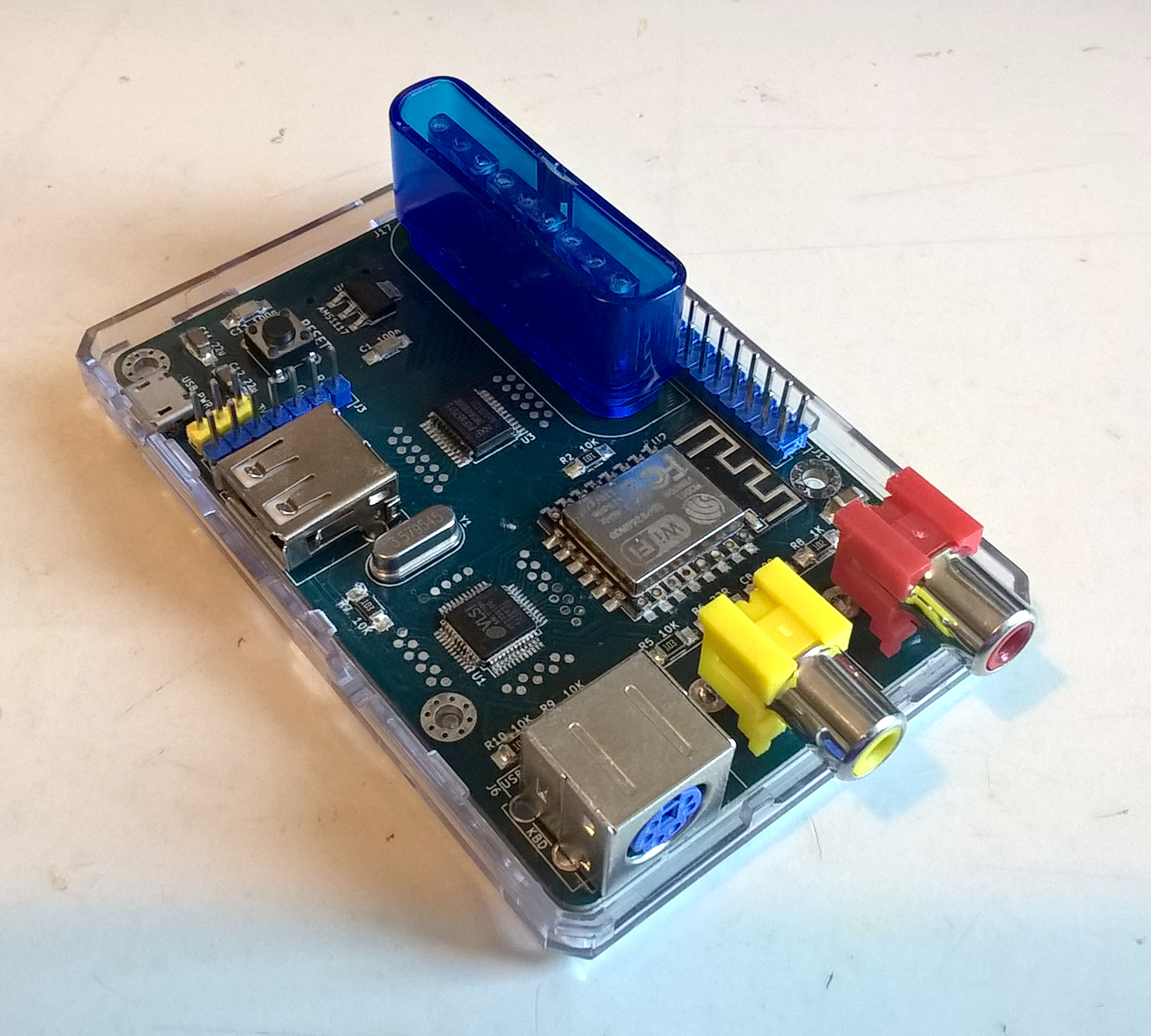
At this point, I made a second prototype, using a custom PCB instead of breadboards, because the first one was infuriatingly unreliable. Not at all sure if I had thought of everything already, I included a pin header for every pin of every integrated circuit to allow me to measure and re-wire things as needed.
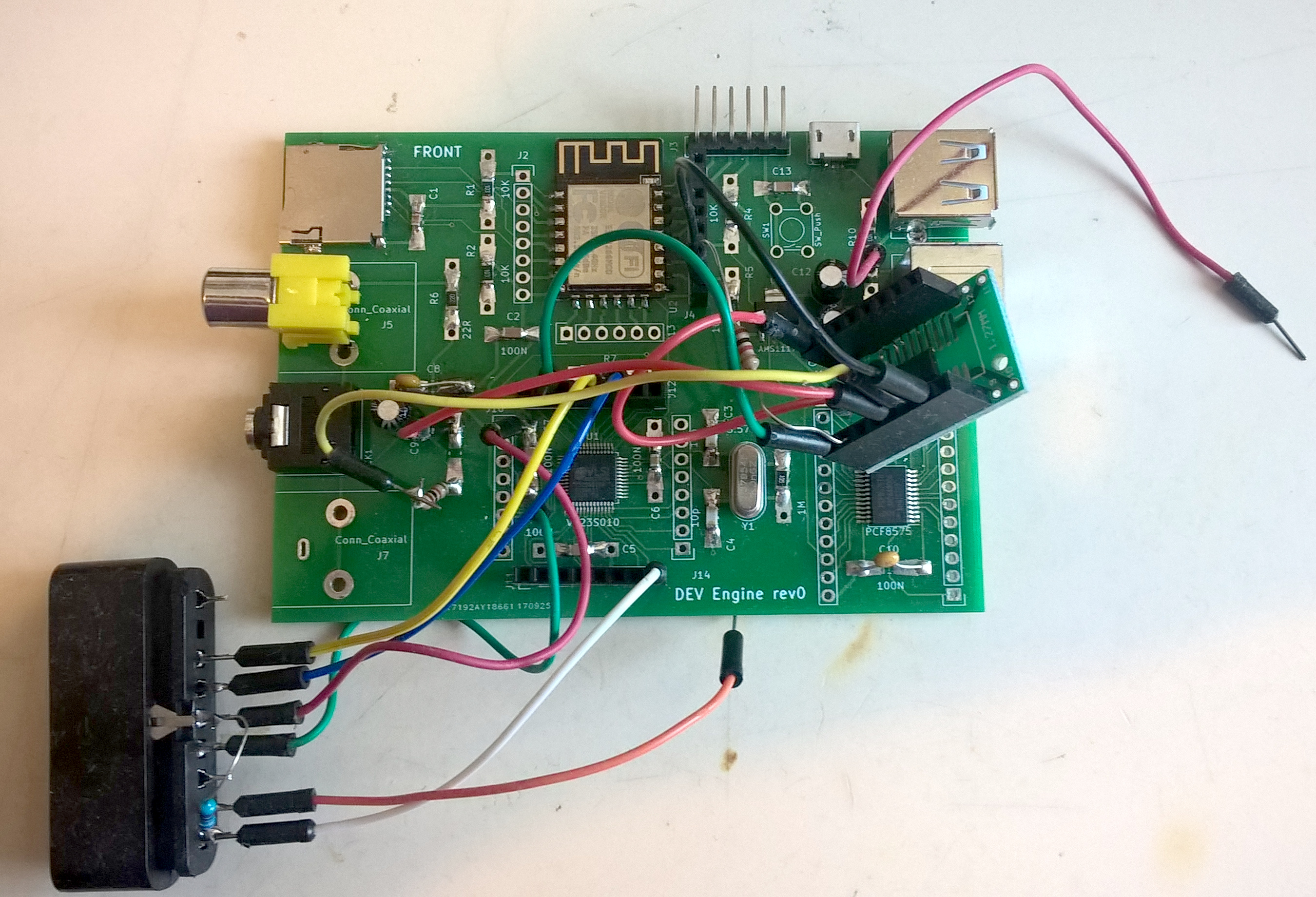
The component suspended in mid-air is a 74HC04 hex inverter.
As you can see here, that turned out to be good idea.
The VS23S010D-L has a "block move" feature, more commonly known as a blitter. It allows you to copy sections of video memory to another location without having to laboriously read all the data into the MCU and then write it back to a different place again. All you have to do is to tell the video chip where to start, where to end, and where to put the copy. While it goes about its business, you are free to concern yourself with other things.
Using the blitter provides a dramatic performance boost in many areas, especially text screen scrolling and rendering of tiled backgrounds. But it only allows for one transfer to happen at a time, and before you start another one, you have to make sure that the last one has finished, or things will go haywire.
There are two ways to check if a block move is still in progress: the MVBLK pin, and a register that can be accessed via SPI. Reading that register over the SPI bus often takes longer than the transfer itself, causing a huge performance hit. The same would be true if I were to connect the MVBLK pin to the I/O expander. There was only one way to check the block move state in a timely fashion: It had to be connected directly to the MCU. But where?
Sharing
I2C devices are a well-behaved bunch. Connect them to a clock and a data line, and they are happy to share it with as many of their peers as you want. They will not make a fuss, and will not speak unless they are spoken to. I wondered if there was a way to capitalize on that, to take advantage of the friendly nature of I2C to wedge in the MVBLK signal.
In the absence of a clock pulse, I2C devices will not do anything, no matter what goes on on the data line, so I figured it would be safe to hook the MVBLK pin up to the latter. I just had to make sure that I2C device access and video block moves do not happen at the same time.
The problem was that the MVBLK signal is active high, i.e. it is on when a transfer is in progress, and off otherwise. At first glance that seems reasonable behavior, but it caused me a big headache. The I2C data line is what is called "open-drain". That means that if a connected device wants to send a "low" signal, it connects the line to ground, and if it wants to send a "high" signal, it disconnects, relying on a shared high-value "pull-up" resistor connecting the data line to the supply voltage to maintain the desired state.
If I hooked MVBLK to the data line, it would perenially drive the line "low", making it impossible for any other device to get any data through. After about a man-year’s worth of concentrated deliberation, I came to the conclusion that there is no way to solve this other than adding yet another chip that inverts the MVBLK signal. Thankfully, the 74HC04 hex inverter is in the five to ten cents price range.
It also helped with another issue: The I2S pin that provides the audio output doubles as the serial port input, which is used when uploading new firmware to the MCU, something I do almost continuously during development. The analog circuitry that smooths the digital audio signal interfered heavily with the serial port data transfer, leading to a great many failed uploads and teeth-clenchings. I did not want to add additional circuitry to avoid that because it did not seem to be of any benefit to the user, but now I could employ one of the unused inverters in the 74HC04 to decouple the analog mushing circuit from the serial port and enjoy reliable 921600 bps transfers again.
Low-cost Housing
At this point—although it took me a while to realize it—the hardware was done: there was nothing to add, and nothing to take away. It was time to make the final board design, the glorious rev1.
You may have noticed that when you walk through a shopping mall in any part of the world, you see only a few places that sell iPhones, but dozens that sell hundreds of different iPhone sleeves. I can’t explain the economics behind that, but I do know that it seems to work the same way for the Raspberry Pi.
AliExpress is full with Raspberry Pi 3 cases, from the dirt cheap to the laughably fanciful. They all have three large cutouts for USB and Ethernet connectors, a smaller one for HDMI, one for a Micro-USB socket, and a long slot for a 40-pin header. The BASIC Engine needed three large cutouts, for audio, video, and PS/2, plus a smaller one for USB-A, one for a Micro-USB socket, and a long slot for an expansion pin header. Close enough.
It also needs a giant cut-out for a PlayStation controller connector, though. The RPi3 doesn’t have anything like that. I decided that learning to dremel builds character. And I really, really didn’t want to design my own case. Really.
So I pulled out the mechanical drawings for the Raspberry Pi 3 and went to re-design the rev0 breadboard replacement so it would fit into an RPi3 case.
And there we are.